No network discussion or network device explanation would be complete without a brief overview of the Open Systems Interconnection (OSI) model. Although this model may seem overly complex, it does have value in our later discussions of attacks, defenses, and infrastructure, as you will see. The OSI model is a general framework that enables network protocols, software, and systems to be designed around a general set of guidelines. Common guidelines allow higher probability of system compatibility and logical traffic flow. In other words, if we all play by the same rules everyone will get along with as few errors as possible.
The OSI model, shown in the left side of Figure 1, has seven layers. As you read through each layer’s function, keep in mind that we are working our way through how data flows. Each layer is connected to the next; this concept will prove valuable as a reference for more advanced data analysis.
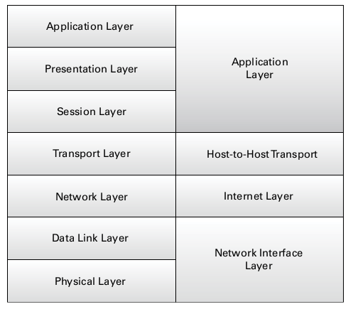
Figure 1 OSI TCP/IP comparative model
- Layer 1: Physical The physical layer consists of the physical media and dumb devices that make up the infrastructure of our networks. This pertains to the cabling and connections such as Category 5e and RJ-45 connectors. Note that this layer also includes light and rays, which pertain to media such as fiber optics and microwave transmission equipment. Attack considerations are aligned with the physical security of site resources. Although not flashy, physical security still bears much fruit in penetration (pen) testing and real-world scenarios.
- Layer 2: Data Link The data link layer works to ensure that the data it transfers is free of errors. At this layer, data is contained in frames. Functions such as media access control and link establishment occur at this layer. This layer encompasses basic protocols such as 802.3 for Ethernet and 802.11 for Wi-Fi.
- Layer 3: Network The network layer determines the path of data packets based on different factors as defined by the protocol used. At this layer we see IP addressing for routing of data packets. This layer also includes routing protocols such as the Routing Information Protocol (RIP) and the Interior Gateway Routing Protocol (IGRP). This is the know-where-to-go layer.
- Layer 4: Transport The transport layer ensures the transport or sending of data is successful. This function can include error checking operations as well as working to keep data messages in sequence. At this layer we find the Transmission Control Protocol (TCP) and the User Datagram Protocol (UDP).
- Layer 5: Session The session layer identifies established system sessions between different network entities. When you access a system remotely, for example, you are creating a session between your computer and the remote system. The session layer monitors and controls such connections, allowing multiple, separate connections to different resources. Common use includes NetBIOS and RPC.
- Layer 6: Presentation The presentation layer provides a translation of data that is understandable by the next receiving layer. Traffic flow is presented in a format that can be consumed by the receiver and can optionally be encrypted with protocols such as Secure Sockets Layer (SSL).
- Layer 7: Application The application layer functions as a user platform in which the user and the software processes within the system can operate and access network resources. Applications and software suites that we use on a daily basis are under this layer. Common examples include protocols we interact with on a daily basis, such as FTP and HTTP.
Two mnemonics that I use to remember the order of layers are:
■ All People Seem To Need Data Processing which uses the first letter of each layer as the first letter of each word in the sentence: Application, Presentation, Session, Transport, Network, Data Link, Physical.
■ Please Do Not Teach Stupid People Acronyms, which does the layers in the opposite order—that is, from the ground up.